- 您现在的位置:买卖IC网 > Sheet目录479 > MMSF7P03HDR2G (ON Semiconductor)MOSFET P-CH 30V 7A 8-SOIC
�� �
�
�MMSF7P03HD�
�POWER� MOSFET� SWITCHING�
�Switching� behavior� is� most� easily� modeled� and� predicted�
�by� recognizing� that� the� power� MOSFET� is� charge�
�controlled.� The� lengths� of� various� switching� intervals� (� D� t)�
�are� determined� by� how� fast� the� FET� input� capacitance� can�
�be� charged� by� current� from� the� generator.�
�The� published� capacitance� data� is� difficult� to� use� for�
�calculating� rise� and� fall� because� drain?gate� capacitance�
�varies� greatly� with� applied� voltage.� Accordingly,� gate�
�charge� data� is� used.� In� most� cases,� a� satisfactory� estimate� of�
�average� input� current� (I� G(AV)� )� can� be� made� from� a�
�rudimentary� analysis� of� the� drive� circuit� so� that�
�t� =� Q/I� G(AV)�
�During� the� rise� and� fall� time� interval� when� switching� a�
�resistive� load,� V� GS� remains� virtually� constant� at� a� level�
�known� as� the� plateau� voltage,� V� SGP� .� Therefore,� rise� and� fall�
�times� may� be� approximated� by� the� following:�
�t� r� =� Q� 2� x� R� G� /(V� GG� ?� V� GSP� )�
�t� f� =� Q� 2� x� R� G� /V� GSP�
�where�
�V� GG� =� the� gate� drive� voltage,� which� varies� from� zero� to� V� GG�
�R� G� =� the� gate� drive� resistance�
�and� Q� 2� and� V� GSP� are� read� from� the� gate� charge� curve.�
�During� the� turn?on� and� turn?off� delay� times,� gate� current� is�
�not� constant.� The� simplest� calculation� uses� appropriate�
�values� from� the� capacitance� curves� in� a� standard� equation� for�
�voltage� change� in� an� RC� network.� The� equations� are:�
�t� d(on)� =� R� G� C� iss� In� [V� GG� /(V� GG� ?� V� GSP� )]�
�t� d(off)� =� R� G� C� iss� In� (V� GG� /V� GSP� )�
�The� capacitance� (C� iss� )� is� read� from� the� capacitance� curve� at�
�a� voltage� corresponding� to� the� off?state� condition� when�
�calculating� t� d(on)� and� is� read� at� a� voltage� corresponding� to� the�
�on?state� when� calculating� t� d(off)� .�
�At� high� switching� speeds,� parasitic� circuit� elements�
�complicate� the� analysis.� The� inductance� of� the� MOSFET�
�source� lead,� inside� the� package� and� in� the� circuit� wiring�
�which� is� common� to� both� the� drain� and� gate� current� paths,�
�produces� a� voltage� at� the� source� which� reduces� the� gate� drive�
�current.� The� voltage� is� determined� by� Ldi/dt,� but� since� di/dt�
�is� a� function� of� drain� current,� the� mathematical� solution� is�
�complex.� The� MOSFET� output� capacitance� also�
�complicates� the� mathematics.� And� finally,� MOSFETs� have�
�finite� internal� gate� resistance� which� effectively� adds� to� the�
�resistance� of� the� driving� source,� but� the� internal� resistance�
�is� difficult� to� measure� and,� consequently,� is� not� specified.�
�The� resistive� switching� time� variation� versus� gate�
�resistance� (Figure� 9)� shows� how� typical� switching�
�performance� is� affected� by� the� parasitic� circuit� elements.� If�
�the� parasitics� were� not� present,� the� slope� of� the� curves� would�
�maintain� a� value� of� unity� regardless� of� the� switching� speed.�
�The� circuit� used� to� obtain� the� data� is� constructed� to� minimize�
�common� inductance� in� the� drain� and� gate� circuit� loops� and�
�is� believed� readily� achievable� with� board� mounted�
�components.� Most� power� electronic� loads� are� inductive;� the�
�data� in� the� figure� is� taken� with� a� resistive� load,� which�
�approximates� an� optimally� snubbed� inductive� load.� Power�
�MOSFETs� may� be� safely� operated� into� an� inductive� load;�
�however,� snubbing� reduces� switching� losses.�
�3500�
�7.0�
�30�
�3000�
�T� J� =� 25� °� C�
�6.0�
�QT�
�2500�
�2000�
�5.0�
�4.0�
�Q1�
�Q2�
�V� GS�
�20�
�1500�
�C� iss�
�3.0�
�1000�
�500�
�0�
�?10�
�V� GS� 0� V� DS�
�10�
�20�
�C� oss�
�C� rss�
�30�
�2.0�
�1.0�
�0�
�0�
�Q3�
�5.0�
�10�
�V� D�
�15� S�
�20�
�25�
�T� J� =� 25� °� C�
�I� D� =� 7.0� A�
�30� 35�
�40�
�10�
�0�
�V� DS� ,� DRAIN?TO?SOURCE� VOLTAGE� (VOLTS)�
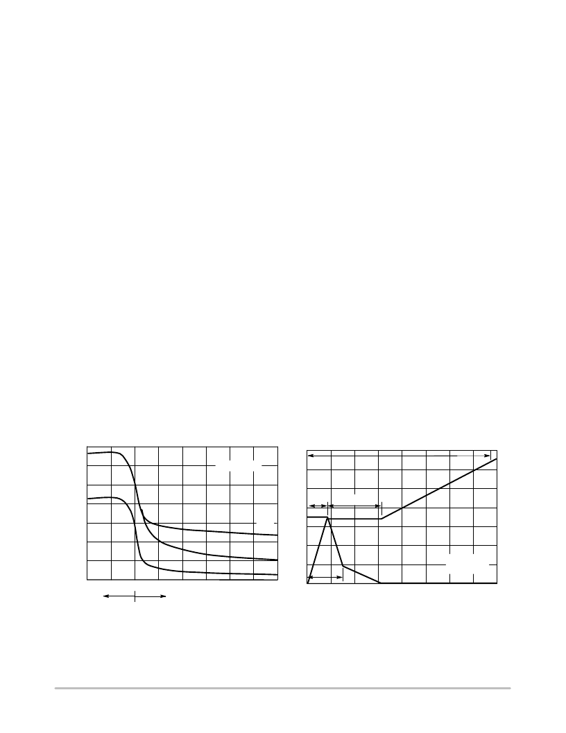
�Figure� 7.� Capacitance� Variation�
�Q� G� ,� TOTAL� GATE� CHARGE� (nC)�
�Figure� 8.� Gate?to?Source� and�
�Drain?to?Source� Voltage� versus� Total� Charge�
�http://onsemi.com�
�4�
�发布紧急采购,3分钟左右您将得到回复。
相关PDF资料
MODEL 700
WELDER STRAIN GAGE 115V
MP100701
SENSOR MAGNETIC W/WIRES THRD
MP101301
SENSOR MAGN PROXY SS HALL EFF
MP101401
SENSOR MAGNETIC PROXIMITY
MP102103
SENSOR MAGN PROXY SS FLANGE MNT
MP6K31TR
MOSFET N-CH DUAL 60V 2A MPT6
MPL015A2T2
IC BAROMETER SPI DGTL MINI 8-LGA
MPVZ5150GC7U
PRESSURE SENSOR VERT 8-DIP
相关代理商/技术参数
MM-SIO-R-01
功能描述:单板计算机 MiniModule Super I/O for CM 730 Legacy IO RoHS:否 制造商:Ampro By ADLINK 外观尺寸:EPIC 处理器类型:Intel Atom D510 频率:1.66 GHz 存储容量:2 GB (max) 存储类型:DDR2, L2 Cache 接口类型:Ethernet, PS/2, SATA, Serial, USB 工作电源电压:5 V, 12 V 功耗:13 W 最大工作温度:+ 70 C 尺寸:165.1 mm x 114.3 mm
MMSKG1
制造商:Siemens 功能描述:
MMSL101
制造商:Preh Elec. 功能描述:
MM-SMART-10
制造商:IDEC Corporation 功能描述:Starter Kit; UL Listed, CE Certified 制造商:IDEC Corporation 功能描述:PROGRAMMABLE LOGIC CONTROLLER; For Use With:MicroSmart series PLCs; Supply Voltage:24VDC ;RoHS Compliant: Yes 制造商:IDEC Corporation 功能描述:MicroSmart Starter Kit For Programmable Logic Controllers 制造商:IDEC CORPORATION 功能描述:MicroSmart Starter Kit w/ FC4A
MM-SMART-10-252
制造商:IDEC Corporation 功能描述:TOOLS, DEVELOPMENT KIT; Kit Contents:4 "; HG1X 2 line O/I, WindLDR WindMSG, Cables & Manuals; For Use With:MicroSmart 10 I/O Module; Operating System Software:Windows 95 / NT 4.0 / 98 / 2000 ;RoHS Compliant: Yes 制造商:IDEC CORPORATION 功能描述:Solution Package PLC HG1X Cabl
MM-SMART-10-HG1B
制造商:IDEC Corporation 功能描述:TOOLS, DEVELOPMENT KIT, Kit Contents:4 ", HG1B RS232/485, 15W Power Supply WindL
MM-SMART-16
制造商:IDEC Corporation 功能描述:Starter Kit; UL Listed, CE Certified 制造商:IDEC Corporation 功能描述:PROGRAMMABLE LOGIC CONTROLLER; For Use With:MicroSmart series PLCs; Supply Voltage:24VDC ;RoHS Compliant: Yes 制造商:IDEC Corporation 功能描述:MicroSmart Starter Kit For Programmable Logic Controllers 制造商:IDEC CORPORATION 功能描述:MicroSmart Starter Kit w/ FC4A
MM-SMART-16-452
制造商:IDEC Corporation 功能描述:TOOLS, DEVELOPMENT KIT; Kit Contents:HG1X 4 line O/I, WindLDR, WindMSG, Cables & Manuals; For Use With:MicroSmart 16 I/O Module; Operating System Software:Windows 95 / NT 4.0 / 98 / 2000 ;RoHS Compliant: Yes 制造商:IDEC CORPORATION 功能描述:Solution Package PLC HG1X Cabl